|
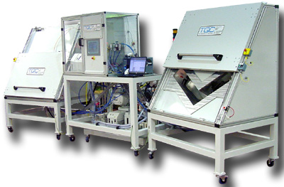
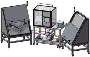
Leak Test Application from TQC Helium Leak Testing of Automotive Fuel Pipes TQC designed and manufactured 2 helium leak test systems for the automatic testing of plastic fuel pipes. The systems included bespoke tooling to accommodate 2 variants of fuel pipe. The helium leak test machine is split into three modules:
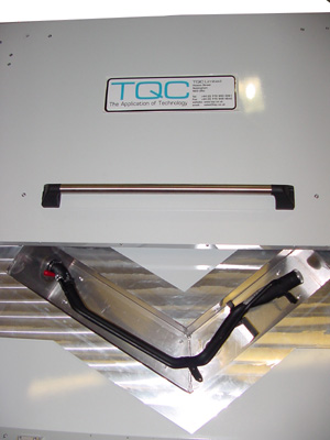
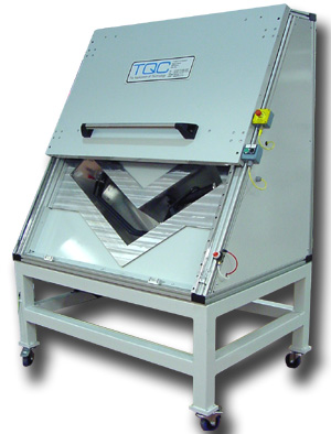
The components are loaded independently into each test chamber, attaching onto the pneumatically expanding seal connector. As each component has three entry points, all of these must all be sealed prior to commencing testing using:
Once the part is sealed correctly, it is placed into the test chamber and over the pneumatically operated expanding seal. The lid is then pulled down over the test chamber to the closed position and the cycle start button operated for that chamber on the centre module HMI. The part is sealed from the chamber and the chamber is sealed from atmosphere. The component is then evacuated to a pre-set level and held there for a time interval to monitor for any large leak created by the pressure differential (termed 'Gross Leak'). A fail at this point will reset the cycle. If the test is passed then both the component and the chamber are evacuated to a lower pre-set level. A fixed volume of Helium is then injected into the component producing a 140mBar pressure differential between the component and chamber. The chamber vacuum line is switched to the mass-spectrometer which monitors for helium leakage from the component into the chamber (termed 'Fine Leak'). A label printer will dispense the appropriate label based upon the data entered by the operator if the test was successful. This is scanned using a hand-held barcode reader for verification. Any components that fail due to gross or fine leaks are held for leak location. The leak location test requires the component to be evacuated, then filled with Helium at 1140mBar Absolute (to produce the 140mBAR pressure differential above atmospheric) A hand-held probe connected to the mass-spectrometer is then used to manually locate helium concentrations indicating leaks in the test component
If you have a current project that you are already looking at, or you are considering improvements to your production in the near future, call us and we will be happy to offer our professional advice & visit you at your site. |
|||||||||||||||
|
Air Decay Leak Testing :: Helium Leak Testing :: Pressure Testing :: Fixture & Seal Design Specialists |
|||||||||||||||